TransmutationsDeBase : Différence entre versions
(premier jet) |
m |
||
| (28 révisions intermédiaires par 2 utilisateurs non affichées) | |||
| Ligne 1 : | Ligne 1 : | ||
| + | {{Projet | ||
| + | |status=Prototype | ||
| + | |status_pub=Publié | ||
| + | |image=20160426 183856.jpg | ||
| + | |description=tableau électrique télécommandé pour performance phytoaquatique | ||
| + | |license=GFDL | ||
| + | |contributeurs=Oli44, | ||
| + | |ingrédients=Arduino, 230V, Bois, Pmma, | ||
| + | |machines=Decoupe Laser, | ||
| + | |source=Découpe laser capot transmutations.svg | ||
| + | |url=https://aniararodado.com/ | ||
| + | }} | ||
=== introduction === | === introduction === | ||
| − | === plans === | + | Pour une performance faisant appel à des chauffe-ballons sans thermostat et des pompes d'aquarium, j'ai conçu un système permettant d'une part de mettre les personnes en sécurité (utilisation d'appareils électriques dans un environnement encombré par des aquariums et des ballons), d'autre part de commander par radio des relais permettant de maintenir les chauffe-ballons à température constante, les éteindre, les mettre en marche forcée. |
| + | |||
| + | == BOM == | ||
| + | |||
| + | === boîtier === | ||
| + | |||
| + | * contreplaqué de bouleau qualité extérieure 9mm de chez Leroy-Merluche (Dispano vend des plaques trop grandes pour passer dans le fourgon) | ||
| + | * * Adaptateur USB A vers B chassis conradpro 1214673 - 62 | ||
| + | |||
| + | === électricité de puissance === | ||
| + | * 6 prises de courant femelle Legrand gamme Mosaic | ||
| + | * 2 plaques 4 modules + support Legrand gamme Mosaic | ||
| + | * un disjoncteur différentiel type A 40A 30mA | ||
| + | * un disjoncteur 16A | ||
| + | * un disjoncteur 10A | ||
| + | * 3 Bornier 8 connexions P+N+T | ||
| + | * Rail DIN de connexion (pris dans un boîtier Legrand 1er prix par ce que ces couillons ne les distribuent pas seuls) | ||
| + | |||
| + | === électronique === | ||
| + | * 1 Arduino Uno | ||
| + | * 6 module relais 250V 7A Tinker it chez snootlab TK-00012 | ||
| + | * 1 Télécommande keyfob 315mhz DFROBOT FIT0355 | ||
| + | * 1 shield télécommande RF 315Mhz DFROBOT TEL0075 | ||
| + | * 1 shield à visser DFROBOT DFR0060 | ||
| + | * câble USB A vers B 25cm e44 | ||
| + | * 6 câble tinker kit 20cm | ||
| + | * transfo USB 5V 1A + câble hacké vers un adaptateur | ||
| + | |||
| + | A la réflexion, il manque un presse-étoupe pour le câble d'alim. La poignée semble inutile. | ||
| + | |||
| + | == plans == | ||
| + | |||
| + | [[Fichier:Découpe laser capot transmutations.svg|240px]] | ||
| + | fichier SVG de la découpe laser du capot. Il faut corriger : élargir de 2.5mm à droite les deux découpes du bas. | ||
| + | |||
| + | [[Fichier:Transmut planche debit mars2016.svg|640px]] | ||
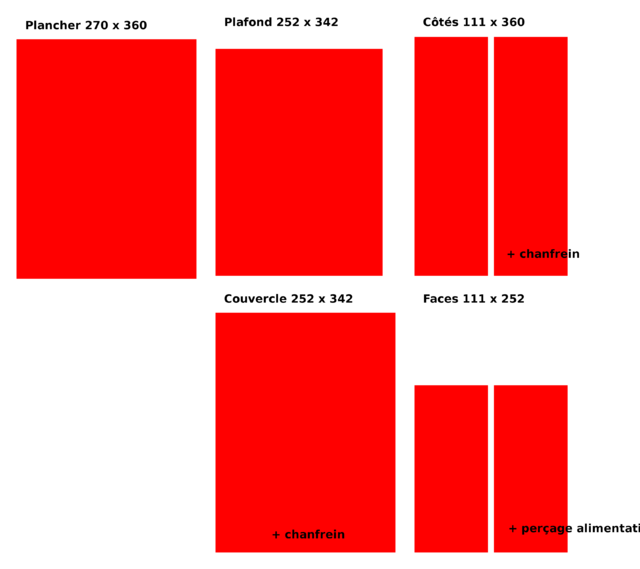
| + | Plan de débit & dessin de la face et du haut du boîtier. | ||
| + | |||
| + | [[Fichier:Transmut arriere mars2016.svg|640px]] | ||
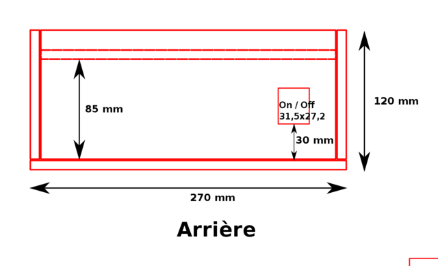
| + | Plan du panneau arrière de la boite. | ||
| + | |||
| + | [[Fichier:Transmut facade mars2016.svg|640px]] | ||
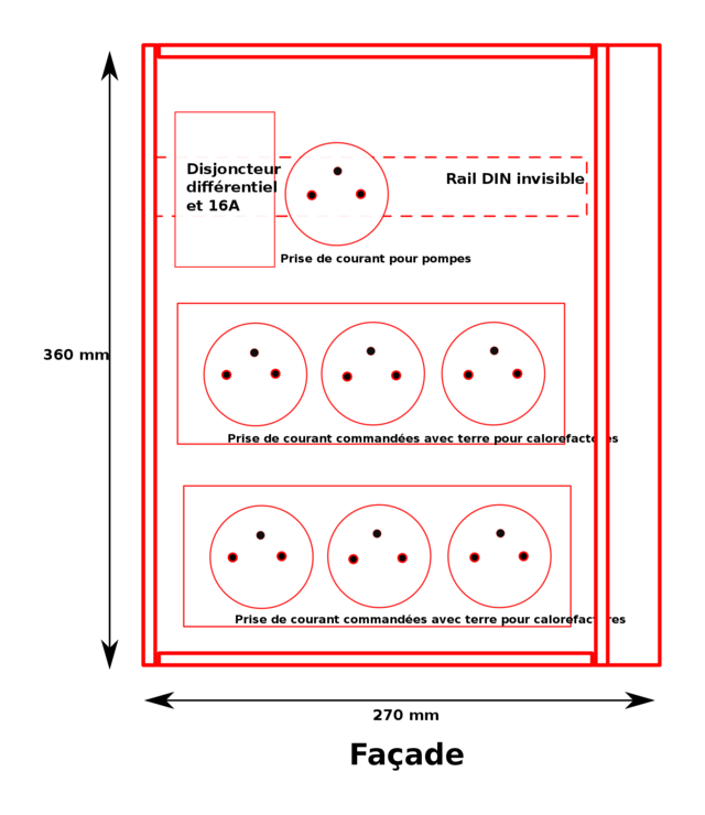
| + | Plan de la face avant. | ||
| + | |||
| + | fichier fritzing du montage Arduino à venir | ||
| + | |||
| + | == code source == | ||
| + | |||
| + | <code lang='C++' linenumbers> | ||
| + | class Cooker | ||
| + | { | ||
| + | byte relaisPin; | ||
| + | unsigned long decalage; | ||
| + | unsigned long intervalle; | ||
| + | |||
| + | byte relaisEtat; | ||
| + | byte cookingEtat; | ||
| + | unsigned long prevMillis; | ||
| + | |||
| + | public: | ||
| + | Cooker(byte pin, unsigned long offset, unsigned long interval) | ||
| + | { | ||
| + | relaisPin = pin; | ||
| + | pinMode(relaisPin, OUTPUT); | ||
| + | |||
| + | decalage = offset; | ||
| + | intervalle = interval; | ||
| + | relaisEtat = LOW; | ||
| + | cookingEtat = 0; | ||
| + | prevMillis = 0; | ||
| + | } | ||
| + | |||
| + | void epochUpdate() | ||
| + | { | ||
| + | prevMillis = millis(); | ||
| + | } | ||
| + | |||
| + | void Update() | ||
| + | { | ||
| + | unsigned long currMillis = millis(); | ||
| + | |||
| + | if ((cookingEtat == 0) && (relaisEtat == LOW) && (currMillis - prevMillis <= decalage)) | ||
| + | { | ||
| + | relaisEtat = HIGH; | ||
| + | digitalWrite(relaisPin, relaisEtat); | ||
| + | Serial.print(int(currMillis / 1000)); | ||
| + | Serial.print(" ColdStart relay "); | ||
| + | Serial.println(relaisPin); | ||
| + | Serial.println(" to "); | ||
| + | Serial.println(relaisEtat); | ||
| + | } | ||
| + | else if ((cookingEtat == 0) && (currMillis - prevMillis >= decalage)) | ||
| + | { | ||
| + | cookingEtat = 1; | ||
| + | } | ||
| + | |||
| + | |||
| + | if ((cookingEtat) && (relaisEtat == LOW) && (currMillis - prevMillis <= intervalle)) | ||
| + | { | ||
| + | relaisEtat = HIGH; | ||
| + | digitalWrite(relaisPin, relaisEtat); | ||
| + | Serial.print(int(currMillis / 1000)); | ||
| + | Serial.print(" Cooking relay "); | ||
| + | Serial.println(relaisPin); | ||
| + | Serial.println(" to "); | ||
| + | Serial.println(relaisEtat); | ||
| + | } | ||
| + | else if ((cookingEtat) && (relaisEtat == HIGH) && (currMillis - prevMillis >= intervalle)) | ||
| + | { | ||
| + | relaisEtat = LOW; | ||
| + | digitalWrite(relaisPin, relaisEtat); | ||
| + | Serial.print(int(currMillis / 1000)); | ||
| + | Serial.print(" Cooking relay "); | ||
| + | Serial.println(relaisPin); | ||
| + | Serial.println(" to "); | ||
| + | Serial.println(relaisEtat); | ||
| + | } | ||
| + | else if ((cookingEtat) && (currMillis - prevMillis >= 10000)) | ||
| + | { | ||
| + | prevMillis = currMillis; | ||
| + | Serial.print("RAZ Cooking relay "); | ||
| + | Serial.println(relaisPin); | ||
| + | } | ||
| + | } | ||
| + | void Stop() | ||
| + | { | ||
| + | if (relaisEtat == HIGH) | ||
| + | { | ||
| + | relaisEtat = LOW; | ||
| + | } | ||
| + | } | ||
| + | |||
| + | void Full() | ||
| + | { | ||
| + | if (relaisEtat == LOW) | ||
| + | { | ||
| + | relaisEtat = HIGH; | ||
| + | } | ||
| + | } | ||
| + | }; | ||
| + | // constants attribution des pins | ||
| + | // 2, 3, 4, 5, 14, 19 | ||
| + | |||
| + | // constantes decalage des cb avant de passer etat 2 = | ||
| + | // 9000; 11400; 12000; 12600; // | ||
| + | // Intervalle de chauffe durant l'etat 2 = | ||
| + | // 1500; 1900; 2200; 3000; // | ||
| + | |||
| + | unsigned int globalState ; | ||
| + | unsigned int prevGlobalState = 0; | ||
| + | |||
| + | unsigned long epoch = 0; | ||
| + | |||
| + | // on instancie | ||
| + | |||
| + | Cooker relais0(2, 9000, 1500); | ||
| + | Cooker relais1(3, 11400, 1900); | ||
| + | Cooker relais2(4, 12000, 2200); | ||
| + | Cooker relais3(5, 12600, 3000); | ||
| + | Cooker relais4(14, 8000, 2200); | ||
| + | Cooker relais5(19, 14000, 3500); | ||
| + | |||
| + | |||
| + | //////////////////////////////////////////////// | ||
| + | /////////////// telecommande RF /////////////// | ||
| + | //////////////////////////////////////////////// | ||
| + | |||
| + | /*The following 4 pin definitions,correspond to 4 buttons on the remote control | ||
| + | //(The telecontroller is Remote Wireless Keynob 315MHz(SKU:FIT0355))*/ | ||
| + | const unsigned int D1 = 8; //The digital output pin 1 of decoder chip(SC2272) | ||
| + | const unsigned int D2 = 9; //The digital output pin 2 of decoder chip(SC2272) | ||
| + | const unsigned int D3 = 10; //The digital output pin 3 of decoder chip(SC2272) | ||
| + | const unsigned int D4 = 11; //The digital output pin 4 of decoder chip(SC2272) | ||
| + | const unsigned int ledPin = 13; //Receiving indicator | ||
| + | |||
| + | volatile int stateRF = LOW; | ||
| + | |||
| + | void setup() | ||
| + | { | ||
| + | Serial.begin(9600); | ||
| + | epoch = millis(); // pour stocker le chrono depuis le démarrage | ||
| + | //========== RF ======================= | ||
| + | pinMode(D4, INPUT); //Initialized to input pin, in order to read the level of | ||
| + | //the output pins from the decoding chip | ||
| + | pinMode(D2, INPUT); | ||
| + | pinMode(D1, INPUT); | ||
| + | pinMode(D3, INPUT); | ||
| + | pinMode(ledPin, OUTPUT); | ||
| + | attachInterrupt(1, blink, RISING); //Digital pin 3,interrupt 1,corresponds to | ||
| + | //receiving interrupt pin of the decoding chip | ||
| + | digitalWrite(ledPin, LOW); | ||
| + | } | ||
| + | |||
| + | void loop() | ||
| + | { | ||
| + | |||
| + | ecouteRadio(); // la commande RF actualise l'etat global | ||
| + | |||
| + | if ((globalState == 1) || (globalState == 2)) | ||
| + | { | ||
| + | relais0.Update(); | ||
| + | relais1.Update(); | ||
| + | relais2.Update(); | ||
| + | relais3.Update(); | ||
| + | relais4.Update(); | ||
| + | relais5.Update(); | ||
| + | } | ||
| + | else if (globalState == 0) | ||
| + | { | ||
| + | relais0.Stop(); | ||
| + | relais1.Stop(); | ||
| + | relais2.Stop(); | ||
| + | relais3.Stop(); | ||
| + | relais4.Stop(); | ||
| + | relais5.Stop(); | ||
| + | } | ||
| + | else if (globalState == 3) | ||
| + | { | ||
| + | relais0.Full(); | ||
| + | relais1.Full(); | ||
| + | relais2.Full(); | ||
| + | relais3.Full(); | ||
| + | relais4.Full(); | ||
| + | relais5.Full(); | ||
| + | } | ||
| + | } | ||
| + | /////////////// les fonctions ////////////////////// | ||
| + | |||
| + | |||
| + | void blink() | ||
| + | { | ||
| + | stateRF = ! stateRF; | ||
| + | } | ||
| + | ////////////////////////////////// | ||
| + | void ecouteRadio() | ||
| + | { | ||
| + | delay(1); | ||
| + | digitalWrite(ledPin, HIGH); | ||
| + | // Serial.print("Locked "); | ||
| + | // Read individually output pins of the decoder chip, | ||
| + | if ((digitalRead(D4) == 1) && (globalState != 0)) // locked icon == stop | ||
| + | { | ||
| + | globalState = 0; | ||
| + | Serial.println("Locked = STOP"); | ||
| + | } | ||
| + | if (digitalRead(D2) == 1 && globalState != 1) // unlocked icon == cold start | ||
| + | { | ||
| + | globalState = 1; | ||
| + | epoch = millis(); | ||
| + | Serial.println("Unlocked : Cold Start"); | ||
| + | } | ||
| + | if (digitalRead(D1) == 1 && globalState != 2) // blitz icon == cooking | ||
| + | { | ||
| + | globalState = 2; | ||
| + | Serial.println("Blitz : Cooking"); | ||
| + | } | ||
| + | if (digitalRead(D3) == 1 && globalState != 3) // alarm icon == full throttle | ||
| + | { | ||
| + | globalState = 3; | ||
| + | Serial.println("Alarm : FULL"); | ||
| + | } | ||
| + | digitalWrite(ledPin, LOW); | ||
| + | } | ||
| + | </code> | ||
Version actuelle en date du 8 juin 2021 à 14:51
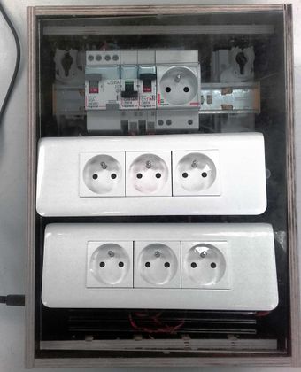
tableau électrique télécommandé pour performance phytoaquatique
Contributeur·ice·s
Statut du projet
Prototype
Statut de la publication
Publié
License
GFDL
Inspiration
Fichiers source
Découpe laser capot transmutations.svg
Machines
introduction
Pour une performance faisant appel à des chauffe-ballons sans thermostat et des pompes d'aquarium, j'ai conçu un système permettant d'une part de mettre les personnes en sécurité (utilisation d'appareils électriques dans un environnement encombré par des aquariums et des ballons), d'autre part de commander par radio des relais permettant de maintenir les chauffe-ballons à température constante, les éteindre, les mettre en marche forcée.
BOM
boîtier
- contreplaqué de bouleau qualité extérieure 9mm de chez Leroy-Merluche (Dispano vend des plaques trop grandes pour passer dans le fourgon)
- * Adaptateur USB A vers B chassis conradpro 1214673 - 62
électricité de puissance
- 6 prises de courant femelle Legrand gamme Mosaic
- 2 plaques 4 modules + support Legrand gamme Mosaic
- un disjoncteur différentiel type A 40A 30mA
- un disjoncteur 16A
- un disjoncteur 10A
- 3 Bornier 8 connexions P+N+T
- Rail DIN de connexion (pris dans un boîtier Legrand 1er prix par ce que ces couillons ne les distribuent pas seuls)
électronique
- 1 Arduino Uno
- 6 module relais 250V 7A Tinker it chez snootlab TK-00012
- 1 Télécommande keyfob 315mhz DFROBOT FIT0355
- 1 shield télécommande RF 315Mhz DFROBOT TEL0075
- 1 shield à visser DFROBOT DFR0060
- câble USB A vers B 25cm e44
- 6 câble tinker kit 20cm
- transfo USB 5V 1A + câble hacké vers un adaptateur
A la réflexion, il manque un presse-étoupe pour le câble d'alim. La poignée semble inutile.
plans
 fichier SVG de la découpe laser du capot. Il faut corriger : élargir de 2.5mm à droite les deux découpes du bas.
 Plan de débit & dessin de la face et du haut du boîtier.
 Plan du panneau arrière de la boite.
fichier fritzing du montage Arduino à venir
code source
class Cooker
{
	byte relaisPin;
	unsigned long decalage;
	unsigned long intervalle;
byte relaisEtat; byte cookingEtat; unsigned long prevMillis;
public: Cooker(byte pin, unsigned long offset, unsigned long interval) { relaisPin = pin; pinMode(relaisPin, OUTPUT);
decalage = offset; intervalle = interval; relaisEtat = LOW; cookingEtat = 0; prevMillis = 0; }
void epochUpdate() { prevMillis = millis(); }
void Update() { unsigned long currMillis = millis();
if ((cookingEtat == 0) && (relaisEtat == LOW) && (currMillis - prevMillis <= decalage)) { relaisEtat = HIGH; digitalWrite(relaisPin, relaisEtat); Serial.print(int(currMillis / 1000)); Serial.print(" ColdStart relay "); Serial.println(relaisPin); Serial.println(" to "); Serial.println(relaisEtat); } else if ((cookingEtat == 0) && (currMillis - prevMillis >= decalage)) { cookingEtat = 1; }
if ((cookingEtat) && (relaisEtat == LOW) && (currMillis - prevMillis <= intervalle))
{
relaisEtat = HIGH;
digitalWrite(relaisPin, relaisEtat);
Serial.print(int(currMillis / 1000));
Serial.print(" Cooking relay ");
Serial.println(relaisPin);
Serial.println(" to ");
Serial.println(relaisEtat);
}
else if ((cookingEtat) && (relaisEtat == HIGH) && (currMillis - prevMillis >= intervalle))
{
relaisEtat = LOW;
digitalWrite(relaisPin, relaisEtat);
Serial.print(int(currMillis / 1000));
Serial.print(" Cooking relay ");
Serial.println(relaisPin);
Serial.println(" to ");
Serial.println(relaisEtat);
}
else if ((cookingEtat) && (currMillis - prevMillis >= 10000))
{
prevMillis = currMillis;
Serial.print("RAZ Cooking relay ");
Serial.println(relaisPin);
}
}
void Stop()
{
if (relaisEtat == HIGH)
{
relaisEtat = LOW;
}
}
void Full() { if (relaisEtat == LOW) { relaisEtat = HIGH; } } }; // constants attribution des pins // 2, 3, 4, 5, 14, 19
// constantes decalage des cb avant de passer etat 2 = // 9000; 11400; 12000; 12600; // // Intervalle de chauffe durant l'etat 2 = // 1500; 1900; 2200; 3000; //
unsigned int globalState ; unsigned int prevGlobalState = 0;
unsigned long epoch = 0;
// on instancie
Cooker relais0(2, 9000, 1500); Cooker relais1(3, 11400, 1900); Cooker relais2(4, 12000, 2200); Cooker relais3(5, 12600, 3000); Cooker relais4(14, 8000, 2200); Cooker relais5(19, 14000, 3500);
////////////////////////////////////////////////
/////////////// telecommande RF ///////////////
////////////////////////////////////////////////
/*The following 4 pin definitions,correspond to 4 buttons on the remote control
//(The telecontroller is Remote Wireless Keynob 315MHz(SKU:FIT0355))*/
const unsigned int D1 = 8; //The digital output pin 1 of decoder chip(SC2272) const unsigned int D2 = 9; //The digital output pin 2 of decoder chip(SC2272) const unsigned int D3 = 10; //The digital output pin 3 of decoder chip(SC2272) const unsigned int D4 = 11; //The digital output pin 4 of decoder chip(SC2272) const unsigned int ledPin = 13; //Receiving indicator
volatile int stateRF = LOW;
void setup() { Serial.begin(9600); epoch = millis(); // pour stocker le chrono depuis le démarrage //========== RF ======================= pinMode(D4, INPUT); //Initialized to input pin, in order to read the level of //the output pins from the decoding chip pinMode(D2, INPUT); pinMode(D1, INPUT); pinMode(D3, INPUT); pinMode(ledPin, OUTPUT); attachInterrupt(1, blink, RISING); //Digital pin 3,interrupt 1,corresponds to //receiving interrupt pin of the decoding chip digitalWrite(ledPin, LOW); }
void loop() {
ecouteRadio(); // la commande RF actualise l'etat global
if ((globalState == 1) || (globalState == 2)) { relais0.Update(); relais1.Update(); relais2.Update(); relais3.Update(); relais4.Update(); relais5.Update(); } else if (globalState == 0) { relais0.Stop(); relais1.Stop(); relais2.Stop(); relais3.Stop(); relais4.Stop(); relais5.Stop(); } else if (globalState == 3) { relais0.Full(); relais1.Full(); relais2.Full(); relais3.Full(); relais4.Full(); relais5.Full(); } } /////////////// les fonctions //////////////////////
void blink()
{
stateRF = ! stateRF;
}
//////////////////////////////////
void ecouteRadio()
{
delay(1);
digitalWrite(ledPin, HIGH);
// Serial.print("Locked ");
// Read individually output pins of the decoder chip,
if ((digitalRead(D4) == 1) && (globalState != 0)) // locked icon == stop
{
globalState = 0;
Serial.println("Locked = STOP");
}
if (digitalRead(D2) == 1 && globalState != 1) // unlocked icon == cold start
{
globalState = 1;
epoch = millis();
Serial.println("Unlocked : Cold Start");
}
if (digitalRead(D1) == 1 && globalState != 2) // blitz icon == cooking
{
globalState = 2;
Serial.println("Blitz : Cooking");
}
if (digitalRead(D3) == 1 && globalState != 3) // alarm icon == full throttle
{
globalState = 3;
Serial.println("Alarm : FULL");
}
digitalWrite(ledPin, LOW);
}

