Switch IRduino : Différence entre versions
| Ligne 13 : | Ligne 13 : | ||
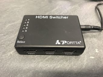
Remplacer le pilotage infrarouge d'un switch hdmi par un arduino pour gérer la sortie | Remplacer le pilotage infrarouge d'un switch hdmi par un arduino pour gérer la sortie | ||
| − | + | === Matériel utilisé === | |
| + | |||
| + | [HDMI switcher PORTTA 5 to 1](https://www.amazon.fr/Portta-Switcher-Commutateur-T%C3%A9l%C3%A9commande-Adapteur/dp/B00GX67TB8/ref=sr_1_4?s=electronics&ie=UTF8&qid=1528794397&sr=1-4&keywords=switch+hdmi+automatique) | ||
| + | |||
| + | === Approche === | ||
| + | |||
| + | - Lire le signal | ||
| + | - Copier le signal | ||
| + | - simuler le signal | ||
| + | |||
| + | == Etapes == | ||
| + | |||
| + | === Etape 1 - Lire le signal === | ||
| + | |||
| + | Le switch dispose de 5 boutons | ||
| + | |||
| + | - bouton 1<br /> | ||
| + | [img]<br /> | ||
| + | 00000001 11111110 01000000 10111111 1<br /> | ||
| + | - bouton 2<br /> | ||
| + | [img]<br /> | ||
| + | 00000001 11111110 00100000 11011111 1<br /> | ||
| + | - bouton 3 <br /> | ||
| + | [img]<br /> | ||
| + | 00000001 11111110 10100000 01011111 1<br /> | ||
| + | - bouton 4 <br /> | ||
| + | [img]<br /> | ||
| + | 00000001 11111110 01100000 10011111 1<br /> | ||
| + | - bouton 5 <br /> | ||
| + | [img]<br /> | ||
| + | 00000001 11111110 00010000 11101111 1<br /> | ||
| + | Après quelques recherche, le protocole utilisé est [NEC](https://techdocs.altium.com/display/FPGA/NEC+Infrared+Transmission+Protocol)<br /> | ||
| + | |||
| + | === Etape 2 - Copier le signal === | ||
| + | |||
| + | === Etape 3 - Simuler le signal === | ||
Version du 4 octobre 2018 à 19:12
Contrôle d'un switch HDMI infrarouge par arduino
Contributeur·ice·s
Statut du projet
Experimental
Statut de la publication
Brouillon
License
Creative Commons Attribution CC-by-sa-3.0 France
Inspiration
Fichiers source
Machines
Matériaux
Lien
Projet irduino
Objectif
Remplacer le pilotage infrarouge d'un switch hdmi par un arduino pour gérer la sortie
Matériel utilisé
[HDMI switcher PORTTA 5 to 1](https://www.amazon.fr/Portta-Switcher-Commutateur-T%C3%A9l%C3%A9commande-Adapteur/dp/B00GX67TB8/ref=sr_1_4?s=electronics&ie=UTF8&qid=1528794397&sr=1-4&keywords=switch+hdmi+automatique)
Approche
- Lire le signal - Copier le signal - simuler le signal
Etapes
Etape 1 - Lire le signal
Le switch dispose de 5 boutons
- bouton 1
[img]
00000001 11111110 01000000 10111111 1
- bouton 2
[img]
00000001 11111110 00100000 11011111 1
- bouton 3
[img]
00000001 11111110 10100000 01011111 1
- bouton 4
[img]
00000001 11111110 01100000 10011111 1
- bouton 5
[img]
00000001 11111110 00010000 11101111 1
Après quelques recherche, le protocole utilisé est [NEC](https://techdocs.altium.com/display/FPGA/NEC+Infrared+Transmission+Protocol)
